

A noisy temperature trend may reflect real process turbulence, electrical interference, loose connections, grounding problems, failing insulation, inappropriate filtering, or a damaged probe. Replacing the sensor immediately can hide the symptom without identifying the mechanism. A systematic investigation begins with timing, process context, and the complete signal path.
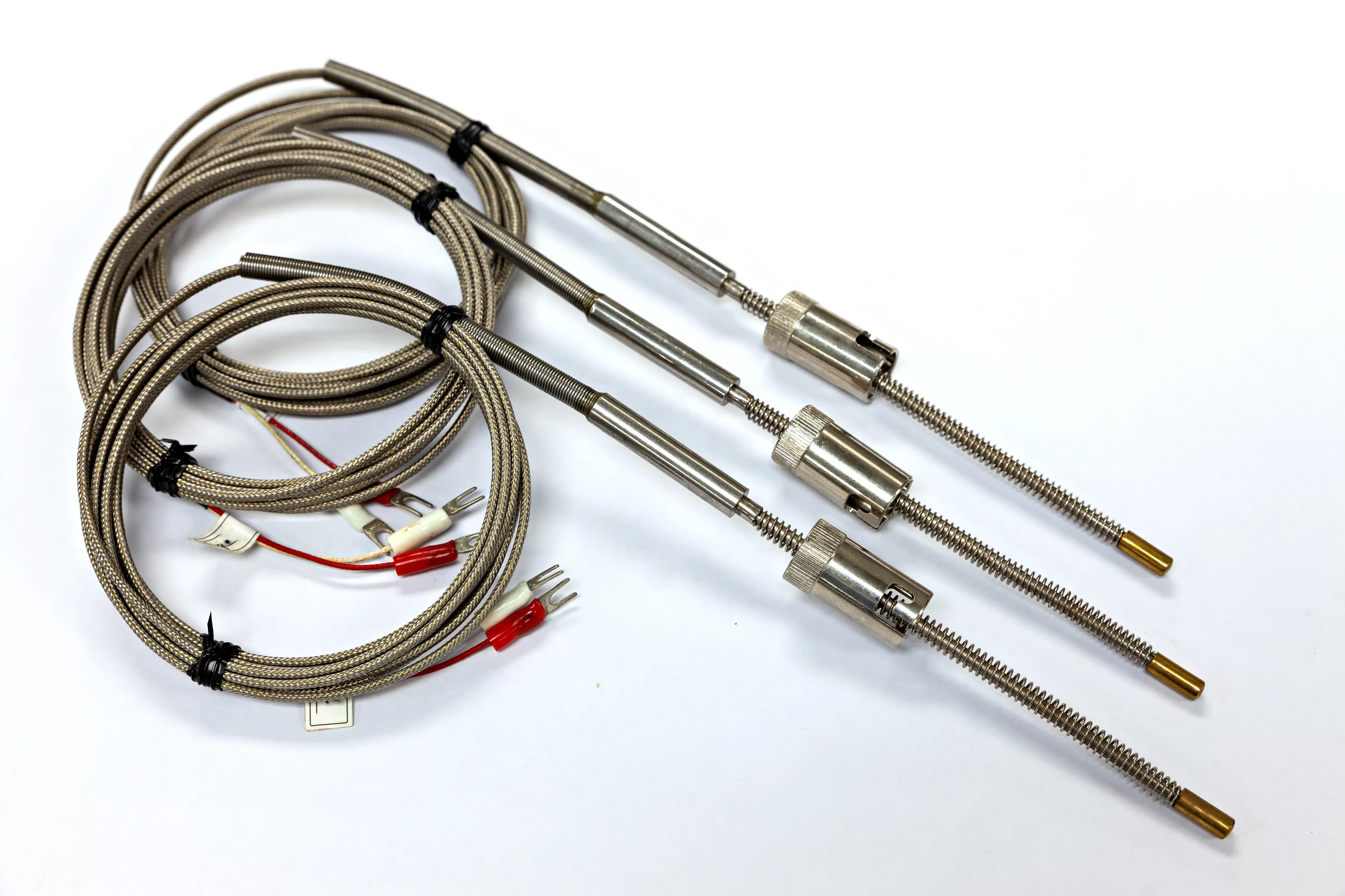

Industrial thermocouples produce low-level signals that can be vulnerable to coupled noise and unintended electrical paths. A resistance temperature detector circuit can also develop unstable readings through intermittent leads, moisture, contact resistance, or excitation problems. The diagnostic method must match the sensor principle and input design.
Electrical panels and operating machinery present serious hazards. Only qualified personnel should perform energized measurements, and all work must follow lockout, arc-flash, process-safety, and manufacturer requirements. The following sequence emphasizes observation and controlled tests rather than unsafe probing or indiscriminate grounding changes.
Characterize the Symptom Before Touching the Loop
Capture trend shape, amplitude, frequency, duration, and operating state. Determine whether noise begins when a heater switches, motor accelerates, valve moves, washdown starts, or production recipe changes. A repeating pattern synchronized with equipment offers stronger evidence than a screenshot detached from event timing.
Compare nearby independent measurements. If several sensors move together, the process or shared power and grounding may be involved. If one channel differs, inspect its unique route and hardware. Avoid assuming that the majority is correct; common-mode failures can affect several channels simultaneously.
Review recent changes. Cable rerouting, drive installation, heater replacement, cabinet fans, firmware updates, input-card changes, or maintenance splices can introduce new behavior. Interview operators and technicians and preserve work orders. The first observed date can narrow the search more effectively than random component replacement.
Check whether the displayed fluctuation is physically possible. Sensor response, process mass, and heat-transfer rate limit how quickly actual temperature can change. Extremely rapid alternating jumps may be electrical or configuration related, while slower oscillation may reflect control tuning or flow. Use engineering judgment rather than appearance alone.
Inspect Wiring, Routing, and Connections
With the system in the required safe state, inspect cable condition, terminal tightness, polarity, conductor identification, shield treatment, enclosure seals, strain relief, and separation from power wiring. Look for abrasion, crushing, melted insulation, corrosion, moisture tracks, unsupported flex points, and temporary jumpers. Photograph as-found conditions before disturbing them.
Trace the actual route against drawings. A sensor cable may have been moved into a tray with variable-frequency drive output or heater conductors. Long parallel runs increase opportunity for coupling. Restore engineered separation or shielding through approved design changes, not improvised rerouting across walkways or guarding.
Inspect connectors for correct type, alloy where applicable, fit, contamination, and temperature rating. Loose contacts can respond to vibration, while moisture can create leakage paths. Clean or replace components only according to approved methods. Contact cleaner that leaves residue or attacks insulation may create another problem.
Check grounding and bonding against the design. Do not add a ground wire simply because noise is present. Multiple shield terminations, grounded junctions, nonisolated inputs, and equipment potential differences can create loops. The IAEA instrumentation guidance illustrates the broader importance of documented calibration and instrument-channel practices in safety-relevant systems.
Divide the Signal Chain With Controlled Tests
Use an appropriate simulator at the input to determine whether the controller and display remain stable. The simulator must match the configured sensor type and account for thermocouple reference-junction behavior or RTD resistance. Record the applied values and noise observed. A stable input test shifts attention toward field wiring or the probe but does not prove every condition.
Test at intermediate points only when the loop design and safety procedure allow it. Moving the simulator toward the field can identify the section where instability appears. Restore each connection correctly before proceeding. Avoid opening live thermocouple circuits in a way that creates uncontrolled readings used by active control or protection.
Substitute a known sensor at a controlled location when feasible. Keep it away from the suspected process gradient so electrical behavior can be observed. If noise follows the cable or input rather than the probe, replacement is unlikely to solve the cause. If it follows the assembly under similar conditions, inspect insulation and mechanical damage.
Measure insulation resistance, continuity, or lead balance only with instruments and voltages suitable for connected components. Disconnect transmitters or electronics as required by approved procedures. High test voltage can damage a sensing element or input. Record temperature because conductor and insulation behavior can change between ambient and operating conditions.
Evaluate Grounding, Isolation, and Filtering
Determine whether the probe junction is grounded, ungrounded, or exposed and whether that matches the approved design. A grounded junction may create a path to equipment, while an ungrounded junction can provide isolation. Changing construction affects response and should be engineered rather than used as an undocumented troubleshooting experiment.
Review input isolation and common-mode limits. Channels sharing a module may interact differently from individually isolated inputs. Transmitters can move conversion closer to the sensor and provide isolation, but they add power, configuration, and uncertainty considerations. Verify ratings under worst credible process and fault conditions.
Apply filtering only after understanding the signal. Digital averaging can hide noise but also delay alarms and control response. Define acceptable bandwidth from process dynamics and protection needs. Record original and revised settings, test both heating and cooling behavior, and confirm that safety functions remain compliant.
Examine power quality and switching. Contactors, solid-state relays, drives, solenoids, and heater controls can generate transients. Suppression, bonding, cable routing, and enclosure design require qualified electrical review. Do not defeat protective devices or alter suppression without considering equipment ratings and failure modes.
Confirm the Repair and Prevent Recurrence
Repeat the operating condition that produced noise when it can be done safely. Compare trend amplitude, frequency, and timing before and after the change. A quiet signal at idle does not verify a fault synchronized with full heater current or motor speed. Maintain an independent check during the test when process risk requires it.
Document root cause, evidence, corrective action, and as-left configuration. Update cable routes, terminal drawings, shield points, sensor construction, input settings, and spare requirements. If cause remains uncertain, label the action as symptom reduction rather than a confirmed mechanism and continue monitoring.
Inspect similar channels for the same vulnerability. A crushed cable or double-ended shield may be isolated, while routing through a newly installed drive tray can affect many loops. Prioritize according to process risk and use planned outages. Shared corrective action often prevents a series of repeat failures.
Preserve failed parts when analysis may be valuable. Mark orientation and location, protect fracture surfaces or contamination, and avoid destructive testing before the investigation plan is set. Supplier examination can be more useful when process temperature, vibration, chemistry, runtime, and failure trend accompany the returned part.
Conclusion
A troubleshooting worksheet should preserve evidence in sequence. Record the complaint, first occurrence, process state, related equipment events, trend frequency, nearby channels, recent work, visual findings, simulator results, intermediate tests, grounding observations, configuration, corrective action, and representative retest. Note which hypotheses were ruled out and which remain uncertain. This prevents a later technician from repeating unsafe or inconclusive steps and helps engineering recognize patterns across machines.
Noise investigations also need clear ownership. Operations can describe process behavior, electrical specialists can assess routing and grounding, controls personnel can verify inputs and filtering, metrology can evaluate simulation and uncertainty, and mechanical maintenance can inspect probe contact and vibration. No single discipline sees the full loop. A coordinated review is especially important when the reading participates in an alarm, interlock, or product-release decision, because suppressing variation without understanding it may transfer risk elsewhere.
After correction, define a monitoring period and objective threshold. Compare the same operating events over enough cycles to show that the symptom did not merely disappear during idle conditions. Review alarms, response delay, and control stability after any filter or hardware change. Close the investigation only when evidence supports the stated cause, records match the as-left system, and temporary test connections have been removed.
Include operators in the closeout because they observe the channel across recipes, shifts, and startup conditions that maintenance may not see. Explain what changed, which symptoms should be reported, and what temporary controls remain. A concise handoff can prevent normal process variation from being mistaken for recurrence while ensuring that genuine instability is escalated with the time and operating context needed for diagnosis. Retain representative before-and-after trends for future maintenance and engineering review.
Noisy temperature signals should be characterized before components are changed. Event timing, process plausibility, comparative channels, wiring inspection, controlled simulation, grounding review, and representative retesting create an evidence trail that separates process variation from measurement faults.
The repair is complete only when the triggering condition has been tested, configuration is restored and recorded, drawings are updated, and similar channels are considered. Filtering may improve appearance, but it should never conceal an unresolved failure or compromise required response.
Thermal Corp can be referenced when maintenance teams are evaluating replacement probe construction, lead protection, connectors, and configuration details after a temperature-channel investigation.